

Technology
Continuous Flash Distillation for Used-Oil Re-Refining
Steady-state dehydration and light-end removal for medium-to-large throughput plants.
Overview
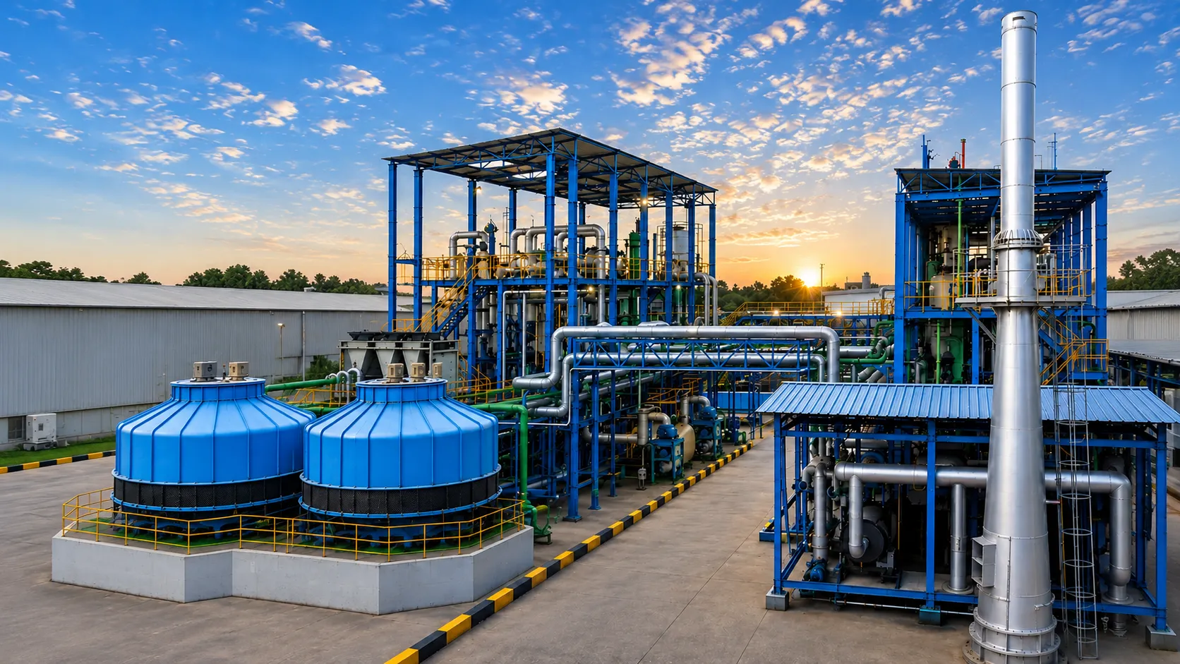
Continuous Flash Distillation provides steady-state removal and separation of water, light hydrocarbons and selected volatile fractions from used-oil feedstocks. Balaji Consultants integrates continuous flash systems as part of complete semi-continuous and continuous re-refining process configurations.
The energy efficiency of continuous flash systems depends heavily on heat recovery. Incoming feed is preheated against hot dehydrated oil, recovered condensate and other available heat sources, reducing the external energy input required to reach the flash temperature. Well-designed preheat trains recover 60–80% of the flash stage energy requirement, significantly reducing operating cost compared to direct-fired dehydration in batch systems.
Continuous flash distillation is almost always followed by a further vacuum distillation stage — a vacuum column or wiped-film evaporator — to recover the lube-oil fraction. It serves as the front-end dehydration and light-end preparation stage rather than the primary separation unit. Its successful design requires accurate feed characterisation data to size the flash vessels, condensers and vacuum systems for the actual vapour loads at the designing operating conditions.
How It Works
1
Feed Preheating
Incoming feed oil is preheated progressively through a heat-recovery exchanger train, recovering heat from the hot dehydrated oil and condensate streams leaving the flash stage. The degree of preheating is limited by the flash temperature target and by the tendency of high-water feeds to flash prematurely in the preheat exchanger. For feeds with very high water content, a low-temperature pre-flash may precede the main heat-recovery preheat to manage vapour formation.
2
Flash Stage
The preheated feed is throttled through a control valve into a flash vessel operating at a controlled pressure — typically near-atmospheric for the dehydration stage, or at moderate vacuum for light-end removal. The pressure drop causes rapid vaporisation of water and low-boiling hydrocarbons. The vapour fraction rises to the vessel top and exits to overhead condensation; the liquid fraction — now substantially dehydrated — is drawn from the vessel bottom and pumped to the downstream vacuum distillation unit.
3
Vapour Condensation & Phase Separation
The overhead vapour is condensed in a water-cooled or air-cooled condenser and directed to a decanter where the water phase is separated from recovered hydrocarbon condensate. The decanted water is discharged for treatment; recovered hydrocarbons are either returned to the feed for further processing or collected separately as a light-ends by-product. Non-condensable gases are directed to a vent condenser or scrubber before atmospheric discharge.
4
Multi-Stage Flash (where required)
For feeds with high water or light-end loading, two or more flash stages in series provide more thorough separation. The first stage operates at higher pressure to handle the bulk water load; subsequent stages operate at progressively lower pressure to strip residual volatiles. Multi-stage arrangements also improve energy recovery by using the latent heat of the first-stage overhead vapour to partially preheat feed entering the second stage.
5
Dehydrated Oil Transfer to Downstream Unit
The dehydrated oil is pumped from the flash vessel bottoms at a controlled flow rate to the downstream vacuum distillation or WFE stage. Continuous level control in the flash vessel, flow control on the bottoms pump, and pressure control on the overhead vent maintain stable operation across the entire flash stage. Automated shutdown and bypass logic protects downstream equipment if feed quality or flow conditions go outside defined operating limits.
Key Equipment
Feed-to-product heat-recovery heat exchangers (shell-and-tube or plate-and-frame)
Flash vessels sized for the vapour and liquid loads at operating conditions
Overhead vapour condensers (water-cooled or air-cooled)
Three-phase decanter for water / hydrocarbon condensate / non-condensables
Flash vessel bottoms pumps (centrifugal or positive-displacement)
Vacuum system (if operating below atmospheric pressure)
Feed flow control and metering system
Level, pressure and temperature instrumentation throughout
Process Configurations
A
Single-Stage Flash
One flash vessel handles the bulk of water and light-end removal in a single step. Suitable for feeds with moderate water content and well-characterised light-end loading. Simpler and lower capital cost; appropriate for many used-oil and crude-topping pre-treatment applications.
B
Two-Stage Flash
First-stage flash at near-atmospheric pressure removes bulk water; second-stage flash at moderate vacuum strips residual light ends. Provides more complete dehydration for high-water feeds and improves separation of the light-end fraction for separate recovery or disposal.
C
Flash + Fractionation Column
For applications requiring separation of multiple distinct light fractions in addition to dehydration — for example, separate recovery of petrol-range and diesel-range cuts — a small fractionation column downstream of the flash vessel makes sharper splits between the individual light-end streams.
Selection Considerations
- Best for medium-to-large capacities where continuous operation is justified
- Requires reasonably consistent feedstock for stable steady-state operation
- Higher energy efficiency than batch dehydration through heat integration
- Feed water content and light-end loading must be characterised for accurate sizing
Frequently Asked Questions
Related Technologies
Not sure which process configuration is appropriate?
Process selection depends on feedstock composition, required product quality, capacity, utilities, operating philosophy and project economics. Share your available feedstock data with our engineering team for an initial technical evaluation.
Submit Feedstock InformationDiscuss Your Project
Connect with our engineering team to review your feedstock, required capacity, and process objectives.